To follow this exercise exactly be sure you've downloaded the [https://surfer.nmr.mgh.harvard.edu/fswiki/FsTutorial/Data tutorial data set] before you begin. If you choose not to download the data set you can follow these instructions on your own data, but you will have to substitute your own specific paths and subject names.
Inspection of Freesurfer Output
In this exercise you will be able to visualize and inspect a good output so that you can become familiar with what the end product should look like. This will step you through visual inspection of a variety of output, but is not necessarily the recommended procedure to take when trying to verify each subject. Some steps are only necessary to check when there are problems. However it is a good idea for new users to become familiar with what the expected output look like and how to view it.
First you need to set your SUBJECTS_DIR to the appropriate place:
setenv SUBJECTS_DIR $FREESURFER_HOME/subjects/buckner_data/tutorial_subjs
Viewing Volumes with Tkmedit
The volumes that are output can be loaded into tkmedit, along with surfaces and the subcortical segmentation. With one command line you can load in the brainmask.mgz and wm.mgz volumes, the rh.white and lh.white surfaces, and the subcortical segmentation.
tkmedit good_output brainmask.mgz lh.white -aux T1.mgz -aux-surface rh.white -segmentation aseg.mgz
You should see a tkmedit window open up to this:BR attachment:good_output1.jpg BR
You are currently looking at the brainmask.mgz (loaded as the main volume) with the surfaces displayed and the aseg.mgz (subcortical segmentation) overlayed. The pial (red line), white (yellow line) and orig (green line) surfaces are all shown. You can toggle between the brainmask.mgz (main volume) and the wm.mgz (aux volume) and you can click on and off the aseg.mgz overlay. To become more familar with the buttons in the Tkmedit Toolbox please read the [wiki:FsTutorial/Tools Freesurfer Tools] section of this tutorial.
Here are the things you can look at while this is loaded in tkmedit:
- intensity normalization
- skull strip
- wm.mgz volume
- the final surfaces
- subcortical segmentation
For the first run through you might find it easiest to toggle off the aseg with the attachment:icon_seg_volume.gif button. Using ctrl-g on the keyboard will have the same effect. You may also find it easier if you toggle off all the surfaces with the attachment:icon_pial_surface.gif, attachment:icon_orig_surface.gif, and attachment:icon_main_surface.gif buttons.
Intensity Normalization
Scroll through the brainmask volume and notice that the intensity is all uniform. You should not see any very bright or very dark spots. If you click on any voxel that is in the wm you can see that it has been normalized to an intensity of (or very close to) 110. The voxel intensity is shown in the Tkmedit Toolbox. This check and the following, Skull Strip check, can be done simultaneously since they both require you to look at features on the brainmask volume.
Skull Strip
Scroll through the brainmask volume and notice that there is no skull left in your image, notice also that the cerebellum is still included in the brainmask volume. You should not see any large areas of skull left behind, or any areas of cortex or cerebellum removed from this volume. You should compare the brainmask.mgz volume to the T1.mgz volume that is also loaded to ensure that the skullstrip has worked properly. You can switch between views in a number of ways, ctrl-1 will show the main volume and ctrl-2 will show the aux, or you can use the buttons attachment:icon_aux_volume.gif and attachment:icon_main_volume.gif. This check and the previous, Intensity Normalization check, can be done simultaneously since they both require you to look at features on the brainmask volume.
White Matter Volume
To check the wm volume you should load it in as a new aux volume. To do this go to File -> Aux Volume -> Load Aux Volume and browse to wm.mgz. This will open the white matter volume, which will look like this:
attachment:wm.jpg
This volume is comprised of all the voxels that freesurfer is calling white-matter, shown in shades of gray. These are the voxels that were normalized to an intensity of, or very close to, 110 as described above. The bright white voxels are voxels that have been added to the volume during the automatic editting of the wm volume. These edits fill the entire ventricle and basal ganglian defect. You can alternate between the wm.mgz volume ( attachment:icon_aux_volume.gif button) and the brainmask.mgz volume (attachment:icon_main_volume.gif button) to see how well freesurfer has classified the white matter.
Final Surfaces
Switch back to the main volume by using the attachment:icon_main_volume.gif button (ctrl-1 on the keyboard will also do this), this will show the brainmask.mgz volume. To check your surfaces you will need to toggle them back on with the attachment:icon_pial_surface.gif for the pial surface, attachment:icon_main_surface.gif for the white surface, and attachment:icon_orig_surface.gif for the orig surface. The surfaces that are overlaid are the pial surface (red line), white surface (yellow line), and orig surface (green line). The orig surface is the "first guess" at the boundary between the white matter and gray matter. After topology fixing and some other steps the white surface is generated. The white surface is the best and final estimation at the boundary between the white matter and gray matter. The white surface and the orig surface will appear nearly identical, but there will be regions where they differ as a result of the topology fixing and smoothing that occurs. The white surface is the surface used in all calculations of thickness so it is important that this surface follows the boundary of the white matter accurately. The pial surface should accurately follow the boundary between the gray matter and the CSF. As you scroll through the slices keep in mind that you are looking at a 2-dimensional rendering of a 3-dimensional image, be sure to look at more than just one view too (i.e., sagittal, coronal and horizontal).
There are regions where the surfaces are not intended to be accurate that you should be aware of. Areas around the hippocampus and amygdala, as well as along the midline cutting plane will often show some inaccuracies. The pial surfaces will not follow the border of the amygdala, instead it will curve inward, mimicing the white surface (see coronal slice 137). Along the midline cut it is possible to see some overlapping of the surfaces from one hemisphere to another.
Subcortical Segmentation
Toggle on the subcortical segmentation with the attachment:icon_seg_volume.gif button. This will show the complete segmentation of the subcortical structures. Each structure is labeled with a unique color/number distinction. If you click on a voxel the structures name and number label will be shown in the Tkmedit Toolbox. Scrolling through the slices you will be able to see that everything is labeled, and done so accurately. Sometimes it is easier to see the structures and their boundaries looking in either the sagittal or horizontal view, so be sure to check around in all of them.
Viewing Surfaces with Tksurfer
Now that you've checked out everything in tkmedit you can close it and begin to inspect the surfaces that are output, for this you will use tksurfer. Tksurfer displays one hemisphere at a time. This exercise will go through visualizing things on the left hemisphere only, but everything works the same on the right hemisphere (except in the initial command you should specify rh instead of lh if you want to look at the right hemisphere). To become more familar with the buttons in the Tksurfer Toolbox, please read the [wiki:FsTutorial/Tools Freesurfer Tools] section of this tutorial.
Here are the things you can look at with tksurfer:
- pial, white and inflated surface
- sulc and curv curvature files
- thickness files
- cortical parcellation
To open tksurfer with the left hemisphere inflated surface of your subject, use the following command:
tksurfer good_output lh inflated
You should see a tksurfer window open up to this: BR attachment:tksurfer.jpg
You are currently looking at the inflated surface. The surface can be rotated using the buttons in the navigation toolbar: attachment:icon_arrow_rot_x_pos.gif attachment:icon_arrow_rot_z_neg.gif attachment:icon_arrow_rot_y_neg.gif attachment:icon_arrow_rot_x_neg.gif attachment:icon_arrow_rot_y_pos.gif attachment:icon_arrow_rot_z_pos.gif
Inflated surface
The inflated surface is good to look at when checking to see if you need to make edits to the wm.mgz volume. You'll notice as you inspect this surface that it is smooth and free from holes, bumps and other defects.
Pial Surface
You can load in other surfaces, and tksurfer will then allow you to switch between them all. The easiest way to do this is to hold down CONTROL and click with the right mouse button on the various surface buttons. To load the Pial Surface hold ctrl and right click the pial surface button attachment:icon_pial_surface.gif a box will pop up where you could browse to the location of the surface you want to load, but it should be already filled in with the path to the lh.pial surface - so you can hit ok. This is what the pial surface will look like:
attachment:pial.jpg
The pial surface is showing you the outer boundary of the gray matter/CSF. This is the same file that was viewed in tkmedit, just represented as a surface image rather than the red outline on the volume. You can inspect this surface by rotating it around as you wish.
White Surface
You can follow the same procedure that you used to load the pial surface for the white surface, except this time hold ctrl and right click the white surface button attachment:icon_white_surface.gif You can inspect this surface by rotating it around as you wish. This is what the white surface will look like:
attachment:white.jpg
The white surface shows the boundary between the white and the gray matter. Again, this is the same file that was viewed in tkmedit just represented differently.
Curv and Sulc Files
Switch back to viewing the inflated surface of the brain by pushing the attachment:icon_main_surface.gif button. You can now load in the curvature file, lh.curv, by holding ctrl and right clicking on the attachment:icon_curv.gif button. The box that pops up will automatically have selected the lh.curv file, so click ok. The curvature file will look like this:
attachment:curv.jpg
This is showing the slightly smoothed mean curvature. It has the untis of 1/mm, and with an outward pointing normal vector field, negative regions are folded out and shown in green (gyral) and positive regions are folded in and shown in red (sulcal)
To view the sulc file you could have changed the dialog box to say lh.sulc, or now you can go to File -> Curvature -> Load Curvature and browse to the lh.sulc file. This will load a slightly different display of green/red values. These are showing the sulcal depth and again here the red regions are sulcal and the green regions are gyral. You can view this as you click on the pial and/or white surfaces.
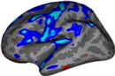
Thickness Maps To view the cortical parcellation it is probably best to toggle off the curvature attachment:icon_curv.gif. To load in the thickness maps go to File -> Load Overlay and browse to the lh.thickness file. This will open up the thickness map that will look like this:
attachment:thickness.jpg
You can adjust the thresholds of the map by going to View -> Configure -> Overlay which will open a new window that will allow you to change the thresholds, try some different settings and see how it affects the display on the map (some options to try min of 1.0 and max of 3.0, min of 2 max of 5, etc). After you change the min and max values be sure to hit apply.
Cortical Parcellations
To view the cortical parcellation it is probably best to toggle off the curvature attachment:icon_curv.gif and thickness files attachment:icon_overlay.gif , and to switch to the pial surface, attachment:icon_pial_surface.gif. You can load the parcellation by going to File -> Label -> Import Annotation and browsing to the lh.aparc.annot file. This will load in the parcellation that will look like this:
attachment:parcellation.jpg
You can inspect the parcellation by rotating the surface to see all sides, you can switch to the inflated view, turn the labels to outline view, whichever way is most comfortable for you to view the parcellations. The parcellation that is loaded here was created with the Desikan-Killiany atlas. By default there are two parcellations that are made when recon-all is run. The second parcellation, called ?h.aparc.a2005s.annot, is created with the Destrieux atlas. The difference is the number and designation of the areas that are labeled. You can load this second parcellation by first going to File -> Label -> Delete all Labels. This will remove the first parcellation. Then you can repeat the steps for loading a parcellation, this time browsing to lh.aparc.a2005s.annot to load the second parcellation.
Using Tkmedit and Tksurfer together
When you are viewing the same subject in tkmedit and tksurfer at the same time (generally done using two seperate terminals, one to launch tkmedit and one to launch tksurfer) you can use some tools to switch from one point on the surface (in tksurfer) to the same point in the volume (in tkmedit). To do this first put your cursor at the point you want in tksrufer. Next, click the save point button attachment:icon_cursor_save.gif in tksurfer. This will save the cursor position. Then in the tkmedit toolbox window click the goto saved point button attachment:icon_cursor_goto.gif . This will now bring you to the same point, only in the volume. This technique is very useful when you see something wrong on the surface of a subject (in tksurfer) and you want to see what is happening in the volume in that same place.