local Gyrification Index (''l''GI)
Overview
Gyrification index is a metric that quantifies the amount of cortex buried within the sulcal folds as compared with the amount of cortex on the outer visible cortex. A cortex with extensive folding has a large gyrification index, whereas a cortex with limited folding has a small gyrification index. The method incorporated into Freesurfer (as the -lGI flag) is based on that of Marie Schaer, [http://ltswww.epfl.ch/~schaer/Schaer_TMI_accepted.pdf "A Surface-based Approach to Quantify Local Cortical Gyrification"], which computes local measurements of gyrification at thousands of points over the whole cortical surface (see also [http://ltswww.epfl.ch/~schaer/Schaer_HBM2007.pdf HBM'07]).
Local Gyrification Index (lGI) is a method adapted from the classical two-dimensional Gyrification Index (2D-GI, (Zilles et al., 1988)), which is the ratio of the total pial cortical surface over the perimeter of the brain delineated on two-dimensional coronal sections. Gyrification Index has been frequently used to quantify cortical folding in clinical population. However, 2D-GI can present threats to accuracy, given that coronal slices do not take into account the inherent three-dimensional nature of the cortical surface. More specifically, perimeter measurements can easily become biased by slice orientation, or by the presence of buried sulci. Also, the use of two-dimensional MRI slices does not allow a precise localization of gyral anomalies. Local Gyrification Index addresses these issues by quantifying Gyrification Index in circular three-dimensional regions of interest.
Local Gyrification Index technique is based on the pial surface extracted from FreeSurfer and includes: (1) creation of an outer hull tightly wrapping the pial surface
attachment:outer_surface.jpg
(2) successive estimations of circular regions of interest on the hull and their corresponding cortical patches,
attachment:circular_roi.jpg
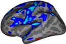
(3) computation of the ratio between areas of both corresponding ROI at each vertex of the hull, (4) propagations of lGI values from the hull to the pial cortical surface.
attachment:individual_lGI_map.jpg
Usage
In freesurfer, use the -localGI flag of recon-all:
recon-all -s <subj> -localGI
This will produce files named lh.pial_lgi and rh.pial_lgi in the subjects surf directory. These files can be loaded as overlays in tksurfer.
Processing Stream
Given a freesurfer surface file (primarily ?h.pial, but ?.white or other surface files are possible), an 'outer surface' surface file is created, called ?h.outer-pial-smoothed, which is basically an 'enveloped' version of the (pial) input. It is created by a morphological closing operation which operates on a volume created using mris_fill (taking as input the pial surface file), using a sphere as the structural element (se).
Once the outer-surface file is available, then the local gyrification measurements are calculated for each vertex of the outer-surface. To do this, circular regions of interest are defined for each vertex on the outer-surface, and the corresponding areas of each ROI are found on the pial surface. Finally, the local gyrification index (lGI) values are calculated at each pial vertices, and a scalar file is output (used in a similar manner as a 'thickness' scalar file).
mris_compute_lgi script internals
Input |
Process |
Output |
Notes |
Computation time |
?h.pial |
mris_fill -c -r 1 |
?h.pial.filled.mgz |
|
<1min |
?h.pial.filled.mgz |
make_outer_surface -se 15 |
?h.pial-outer |
matlab commands, morphological closing (see note 1. below) |
<2min |
?h.pial-outer |
mris_extract_main_component |
?h.pial-outer-main |
|
<1min |
?h.pial-outer-main |
mris_smooth -nw -n 30 |
?h.pial-outer-smoothed |
|
<1min |
?h.pial-outer-smoothed |
mris_convert -n (output normals as ascii) |
?h.pial-outer-smoothed-normals.asc |
|
<1 min |
?h.pial, ?h.pial-outer-smoothed |
find_corresponding_center_FSformat |
?h.pial.*.center |
matlab commands |
<1 min |
?h.pial, ?h.pial-outer-smoothed, ?h.pial-outer-smoothed.asc |
make_roi_paths |
?h.pial.*.path |
matlab command (see note 2. below) |
~1h |
?h.pial.*.path, ?h.pial.*.center |
mri_path2label |
?h.pial.*.label |
see note 3. below |
per vertex: 17.5 s in average, total: ~2h (but probably 5s per vertex are devoted to read the surface only, which is done up to 1'000 times) |
?h.pial, ?h.pial-outer-smoothed, ?h.pial-outer-smoothed-normals.asc, ?h.pial.*.labels, ?h.pial-outer-smoothed-mesh |
compute_lgi |
?h.pial_lgi.asc |
matlab commands (see note 4. below) |
average per region: ~3s, total: ~45min |
?h.pial_lgi.asc |
mris_convert |
?h.pial_lgi |
final output |
<1 min |
Notes on stages
1. Diameter of se sphere
Decreasing the diameter of the se sphere below 10mm will produce an outer surface entering in the sulci. Increasing it does not substantially affect the morphology of the outer surfaces (but increase computation time!).
2. Computation of the regions of interest on the outer surface in matlab (=make_roi_paths)
For each one of 100 vertex of the outer surface (that we denote iV), a circular region of interest is defined (referred as ROIo in the validation paper). The area of this region will become the above term of the lGI ratio computation at that vertex. Based on intersection with a sphere with a geodesical constraint. Seed points are defined as the vertex of the pial surface which is closest to the iV on the outer surface.
3. Computation of the regions of interest on the outer surface using FreeSurfer (=mri_path2label)
For each region of interest on the outer surface (ROIo), a corresponding region of interest is obtained on the pial surface (referred as ROIp in the validation paper). The correspondance is based on both the proximity with the ROIo's perimeter and geodesical constraints.
4. Computation of the lGI measurements and creation of cortical gyrification maps in matlab (=compute_lgi)
lGI values sampled on the outer surface. lGI values are weighted according to their prior involvement in the whole computational process with weighting inversely proportional to the distance to the outer surface's normal.